Railways - for a change
My interest in radio, and electronics more generally started when I was about 6 years old. Interest in railways came shortly after but more so was an interest in telegraphy. I suspect that came from listening to morse signals. Anyway, however it came about the telegraphy side of things coupled with my railway interest via railway signalling when I was invited into a sigal box and saw the various telegraphy kit.
Fast forward a few decades and an entire unrelated career and I find myself working on a heritage railway in the - you guessed it - Signal and Telegraph department. So, and in keeping with the title of my blog here are a couple of work pictures...
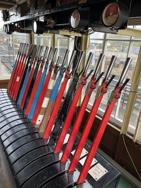
The lever frame. Both mechanical and electrical interlocking is used here in order to ensure conflicting routes cannot be set. The mechanical interlocking is behind the levers under cover and the electrical interlocking is under the floor.
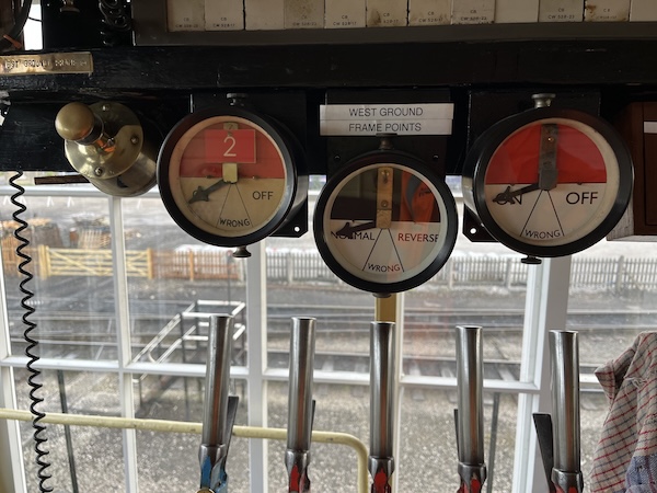
These indicators show the state of signals (on or off) and points (normal or reverse) plus 'wrong'. The instruments use DC coils so that a single wire to whatever is monitored can be used with a polarity reversal to indicate the two states. The 'wrong' indication results from a loss of voltage, either due to a fault or due to whatever is being monitored being in an incorrect state, rather critical in most cases! At the far end, take a signal for example, a switch is employed which feeds a positive if, say the signal arm is off (clear) or a negative if it is on (danger - stop). The indicator swings through 'wrong' as the arm moves so the signaller has a visual feedback for signals that cannot be observed from the signal box.
The electrical side of things is a mixture of AC or DC power supplies and batteries, plus relays, assorted contactors, fuses and lots, and lots of wire.