Railway homework
Another of my hobbies, if you can call it that is that I volunteer at a heritage railway in the Signal and Telegraph (S&T) department. We maintain the signalling along the 4.5 mile railway which includes three signal boxes and numerous signals, points and telephones.
Occasionally I get homework. This week it is working out the resistance needed to drop the voltage across the track at one point to a level suitable to power a relay. This is for a track circuit, in the case in question across a set of points. With the track circuits we use the section of track concerned, which is isolated from the rest of the railway by insulated block joints separating the bits of rail, power is fed to the rails at one end and a relay is connected at the other. The voltage needs to be sufficient to keep the relay up and this indicates that there is no train on that section of rail. When a train is on that track the voltage is shorted out across the wheels and the relay drops to indicate the presence of a train.
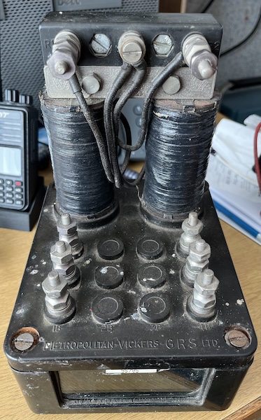
The relay concerned is similar to the one shown below and has a coil resistance of around 9 ohms. Typically this will be held up ('picked' or energised) at 1V or less with a resistance in circuit ti ensure the relay operates correctly and to keep the current down so the power supply (a battery in some cases) does not complain if the train remains on the track.

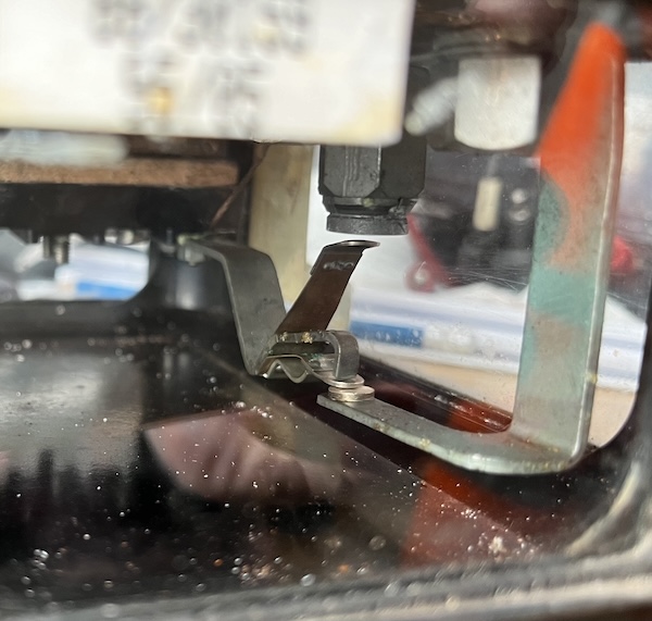
These older style relays are quite large and this makes it easy to see if the contacts are up (picked) or down as below...

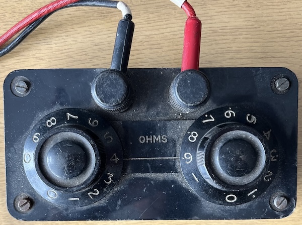
Testing a track circuit is done by a drop shunt, basically a resistance box that is connected across the track to see when the track relay drops (train on line) and picks again (line clear). The values of this vary with the weather but on one of our points the relay drops at 1.4 ohms and picks again at just over 2 ohms. The condition of the rails, dampness etc. all affect this.
